The beginning of a container transfer often looks uneventful. The final portion reveals whether the installation was designed for the whole batch: the source level falls, flow becomes less consistent and the operator has to decide when to stop.
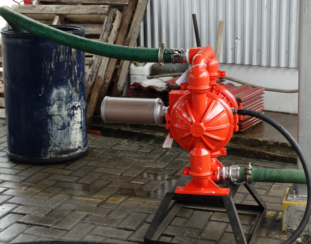
A diaphragm pump for IBC unloading should be assessed at the lowest normal liquid level. The same end-point questions apply when specifying a diaphragm pump for drum unloading, although the container connections and pickup arrangement differ.
That decision affects both recovered product and utility use. Continuing to cycle after useful transfer has ended can consume air without moving meaningful liquid. Stopping too early leaves product behind. A reliable unloading arrangement needs an agreed end point and an inlet arrangement that remains workable as the vessel empties.
Assess a diaphragm pump for IBC unloading at low level
For a pump drawing from above the liquid surface, the static lift changes as the level falls. For a bottom-connected IBC, the available positive head reduces. In either arrangement, the hose route, valve and actual connection bore remain important. A layout that works with a full container may become marginal near the end.
Keep the inlet route practical and identify high points where gas can collect. Check that the hose is suitable for suction service and cannot collapse under the expected conditions. A visible external diameter does not establish the hose's internal bore or suitability.
The container also needs an approved way to accommodate volume leaving it. Manufacturer safety guidance warns that inappropriate vessel ventilation can expose a container to damaging pressure conditions. For hazardous or contamination-sensitive fluids, use the vessel's engineered venting or closed-transfer arrangement; casually opening a lid is not a general solution. [R10]
Define “empty” as an operating requirement
Specify acceptable residual quantity and how it will be measured. The residual may include liquid in the container, pickup arrangement, pump and connected hose. Different measurement boundaries can make two installations appear to recover different amounts even when they deliver the same useful quantity downstream.
Avoid a blanket promise of complete emptying. Container geometry, pickup position, product adhesion and the permitted handling method all affect residual volume. Changing the container's position or using an improvised lifting arrangement to recover the last liquid is not a substitute for a suitable unloading design.
| End-of-batch issue | Evidence to collect | Possible engineering response |
|---|---|---|
| Flow falls before the expected end | Remaining source quantity and inlet condition | Review restriction, level and pickup geometry |
| Cycling accelerates with little delivery | Delivered volume and source-level trend | Review an approved empty-source stop method |
| Batches leave inconsistent residuals | Residual measurement with a fixed boundary | Standardize the unloading and measurement method |
| Transfer foams near completion | Observation of gas entry and return arrangement | Review the pickup and end-point strategy |
Choose a stop signal that answers the right question
A level sensor can indicate that the source has reached an agreed level. A receiving-vessel measurement can demonstrate that a target quantity arrived. An over-run control can respond to a specified abnormal cycling condition. These functions are related but not identical.
ARO lists level-control and over-run accessories for compatible installations. Their availability supports a more controlled unloading sequence, but selection still requires confirmation of the pump model, fluid environment and desired shutdown action. [R4]
A cycle count by itself is an uncertain empty-container signal because effective liquid displacement changes when gas enters. Where quantity matters, establish an independent delivery check and document the expected accuracy.
Leave the system ready for its next batch
After transfer, follow the approved isolation, pressure-release and cleaning procedure. Account for trapped liquid before disconnecting a hose. Graco's operating instructions illustrate the need to relieve stored pressure and flush with a compatible medium where required; the exact sequence must come from the installed model's documentation. [R11]
For an unloading enquiry, send WILLEE the container outlet arrangement, fluid information, pump position, hose length and acceptable residual quantity. Those details reveal more than a request for “a pump for a 1,000-litre tank.”
Review a drum or IBC transfer arrangement
Technical references
[R10] Wilden / PSG. Safety Supplement to Engineering, Operation and Maintenance Manual.
[R11] Graco. 308981ZAZ: Air-Operated Diaphragm Pumps – Instructions.
[R4] ARO. Diaphragm Pump Controls.
Application photographs are manufacturer reference images, not WILLEE customer-project claims. Model-specific instructions take precedence over this general engineering discussion.
Select the pump against a documented transfer route and acceptance requirement.
相談先: Kevin機器の正確な仕様に対応する取扱説明書と仕様書を使用してください。この記事は、選定を検討する際の導入となる情報を紹介しています。