Commissioning a Diaphragm Pump: A Repeatable Site Acceptance Test
A diaphragm pump installation guide for site acceptance: test conditions, traceable readings, startup checks and an agreed performance baseline.
Executive summary
A pump can start, cycle and pass a brief water check without demonstrating that it will complete the production duty. Site acceptance should connect the purchase requirement with a documented operating condition and measurable result.
This diaphragm pump installation guide focuses on acceptance evidence after the installation requirements have been established. It helps connect commissioning observations to the agreed process duty.
This paper proposes a practical acceptance framework for diaphragm transfer pumps. It is an engineering planning guide, not a published certification standard, a pressure-test procedure or a substitute for the manufacturer's commissioning instructions. Acceptance criteria must be agreed by the purchaser and supplier before testing.
1. An installation guide needs a testable acceptance question
Replace “the pump works” with a specific requirement. For example: transfer an agreed batch volume within an agreed time, at the defined source level and product condition, while remaining within the equipment's operating limits. The actual numbers belong in the purchase specification and test sheet.
Identify what is being accepted: the pump alone, a supplied skid or the complete installed system. A pipe restriction supplied by another contractor can prevent the system from meeting the duty without proving a pump defect. Conversely, passing a workshop test does not prove that the installed arrangement is satisfactory.
2. Freeze the configuration under test
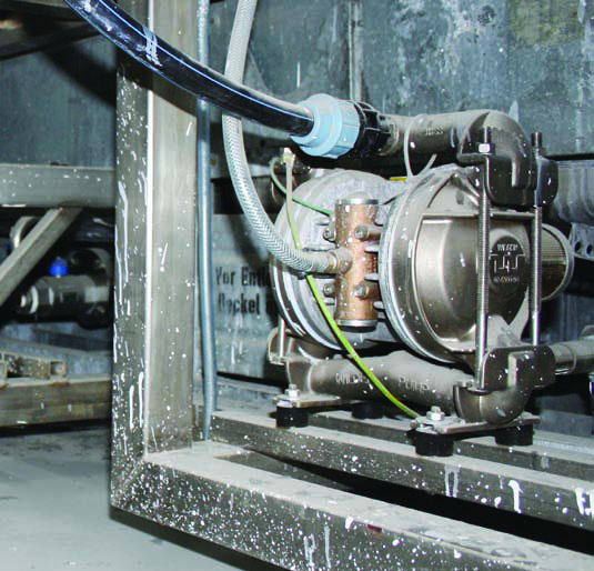
Record the manufacturer's full model designation, serial number where present, materials configuration and the manual revision used. Photograph the installed inlet, discharge, air or electrical supply, instruments and support arrangement. Include valve positions and any accessories that affect flow or control.
Confirm that the installed equipment and operating environment match the selected configuration. Required site controls, isolation and pressure-relief arrangements must already be in place. Manufacturer manuals provide model-specific starting instructions and limits; the test plan must work within them. [R10, R11]
A test using temporary oversized hoses may be useful for diagnosis, but it does not establish acceptance of the final installed pipework. Label temporary arrangements clearly and repeat the relevant checks after reinstatement.
3. Agree the minimum data set
| Field | Entry required before the test | Why it matters |
|---|---|---|
| Fluid | Identity, temperature, density and relevant viscosity | Defines the process condition |
| Source | Starting and ending level; vessel pressure where relevant | Documents changing inlet duty |
| Discharge | Destination condition and pressure measurement point | Defines the resistance being overcome |
| Utility | Dynamic air pressure and flow, or electrical input as applicable | Identifies available driving input |
| Delivery | Volume or mass, elapsed time and measurement method | Demonstrates useful output |
| Instruments | Identification, range and calibration status | Supports traceability |
| Konfiguration | Pump code, accessories and operating settings | Makes a repeat run meaningful |
If water is used for a preliminary check, describe exactly what it verifies. It may help confirm operation and detect visible leakage, but it does not validate the viscosity, chemical behavior or solids handling of the production fluid. Establish an approved transition and cleaning process before product introduction.
4. Use a small test matrix
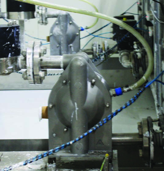
Choose representative operating cases instead of taking many readings at one easy point. A transfer installation may require a normal-duty run, a low-source-level run and an approved restart check. A controlled batch process may require additional verification of its stop condition and delivered quantity.
A plant with narrow operating variation may need fewer cases. A duty with large temperature or backpressure changes may need more. The selection should follow the process risk and purchase requirement, not an arbitrary requirement to collect a fixed number of tests.
| Test case | Condition to define | Result to compare with the agreed limit |
|---|---|---|
| Normal transfer | Representative fluid and source level | Delivered quantity and transfer time |
| Lowest normal source level | Realistic end-of-batch inlet condition | Sustainable delivery and stable operation |
| Highest normal discharge resistance | Approved downstream condition | Required output within operating limits |
| Restart | Defined stop period and normal restart sequence | Repeatable return to service |
| Control response | Approved simulation or functional check | Correct stop, indication and restart permissions |
Do not create a hazardous blocked line, overflow or diaphragm rupture simply to test a control. Use the manufacturer's approved functional-check method and the site's authorized procedure.
5. Keep raw observations and calculations separate
Retain start and finish readings, elapsed times and operator notes. Calculate delivery from those values in a separate field. If tank mass is used, note the tare method and density used to infer volume. Record fluctuations rather than replacing them with a single favorable number.
Repeat a run when an unexplained difference appears. Compare source level, temperature, utility pressure and valve positions before declaring an equipment change. Wilden's installation guidance identifies suction integrity and piping arrangement as performance factors, so those conditions belong in the record. [R7]
Instrument uncertainty must be small enough to distinguish an acceptable result from an unacceptable one. If a required transfer rate lies close to the measured value, an approximate tank graduation and a casual stopwatch reading may not settle the question. Agree how borderline results will be resolved before the test.
6. Classify the outcome, not just pass or fail
Use three findings: accepted, accepted with a documented limitation, or corrective action required. A limitation should identify the exact condition, its operational consequence and who has accepted it. It should not silently redefine the purchase requirement after testing.
For a shortfall, distinguish utility supply, inlet arrangement, downstream resistance, control sequence and equipment condition. Record the evidence for each suspected cause. Change one relevant factor at a time when practical, so a successful rerun explains what improved the result.
7. Hand over a usable baseline
The final file should contain the configuration, test conditions, raw readings, calculations, deviations and responsible sign-off. Attach photographs and the applicable manual reference. Retain an operating baseline for later maintenance comparisons; it is more useful than a statement that the pump “ran normally on installation day.”
WILLEE can help turn a pump enquiry into a testable duty by clarifying fluid, quantity, transfer time, pressure conditions and connection details before ordering. Acceptance is simplest when the specification already explains what success looks like.
Prepare a pump duty and acceptance enquiry
Technical references
[R7] Wilden / PSG. PS8 Plastic Engineering, Operation and Maintenance Manual.
[R10] Wilden / PSG. Safety Supplement to Engineering, Operation and Maintenance Manual.
[R11] Graco. 308981ZAZ: Air-Operated Diaphragm Pumps – Instructions.
Application photographs are manufacturer reference images, not WILLEE customer-project claims. Model-specific instructions take precedence over this general engineering discussion.